Friday, February 24, 2012

Helix Pt2

Found this on youtube when I was looking at some N Scale layout videos, I think it's funny but I am sure there are some out there who get really really excited about it, the kato track stands up pretty well. LOL


On to less exciting stuff and I have been busy cutting and building the base and supports for the helix as well as determining the final placement by doing a more detailed plan for the helix.
The picture below shows the plan for the helix support from the top down it will be 1200 x1400 mm the track will come from the bottom of the other side of the layout and climb the helix to the upper level, then it will go back across the gap to the helix and down to the lower level. The helix will also have access to the staging tracks. I did a plan at work to find out how many loops I will need to get to the second level but I lost it but from memory it is about 5.5 loops.
You may have seen in the previous post marking out the curves to cut for the helix and then I realised I have a router so I just made a jig with two screws to alter the diameter of the cut.

To get the most out of the boards I made a jig on an old table to cut curves from the off cuts, I just screw the board to the table and cut them with the router.

The benchwork for the helix is nearly finished as well just needs some paint.


The photo below shows the gap leading to the staging yard.
Test fittting the helix sections.


Monday, January 30, 2012

Start the Helix

G'day all I have been busy over the summer with a wedding in Thailand and some house maintenance to do but I am back in the layout room and starting the helix planning and construction. While my wife and daughter were in Thailand for an extra month I took the opportunity to chase some trains.

 The helix will be double track with an outside diameter of 120cm and will rise about 75mm per turn which will give it a grade of just over 2.1% or so the web sites that have grade calculators tell me. I would like to thank all the people who have posted helix charts and designs online you don't have to do it but I has helped me a lot and I am sure that many other modelers have applied what they have studied on your posts. I have been a member of a club where the most common skill was the keeping of knowledge lest somebody do it better than you.
I drilled some holes in a stick of timber to draw the right diameter helix pieces on 6mm MDF board and will
glue the sections together over lapping so there is no need to add joints. Why MDF ?, only one reason it is cheap $20 for a 2400 x 1200 sheet. I will paint it to keep out the moisture to prevent sagging.
To use most of the MDF board I will cut two types of pieces a 45 and a 90 degree section I made a template from some scrap for the 45 degree section to place over the off cuts.
A mock up of the helix location, it helped me to decide to make the base then slip in the helix for ease of construction. I was quite surprised about the size of it, looked smaller on the plan.
I will support the helix decks with some brackets because they are easy to adjust to where I want them and there are no joints to support.

Thursday, October 27, 2011

More Bench Work

In a slight change of plan I have decided to put some timber up between the supports  so the background will only have to be flush with it and not have slots cut in it to go around the supports.
I got some angle strips and masonry screws to secure the supports to the wall to make it more stable.
Because it is tall and narrow I have also bolted the east side of the bench work to the floor.

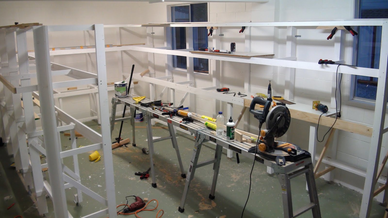
The layout bench work 95% complete and painted, in the foreground is the location of the Helix.
East side bench work.


Saturday, October 1, 2011

Lighting The Layout


I have finished painting the supports for the west section of the layout and I am in the process of fiddling with the final placement.

I decided to play around with the lighting for the layout just to check that I made the right choice and because I am sick of wood working at the moment. The photo above is the just the room lighting on some test wagons on the second level.

I was thinking for a while about how I was going to light the layout and for while I was focused on single tube fluro lights but the cheapest one that came with its own plug was about thirty five dollars. Then I had a brain wave when I was in bunnings and came across a string of party lights with incandesant bulbs for twenty bucks. What if I replaced the bulbs with 23W compact fluro bulbs which would be 2w under the max rating for each light socket and I didn't have to wire them up just plug them in. The lights are spaced 700mm apart and have a three meter cord from the socket to the first light. I have tried a few styles of CF bulbs and have settled on Cool White 2700K for the effect I want.

Test wagons in the middle of the deck.


Test wagons on the edge.

Test wagons about two inches from the back.

Test wagon in the middle.

Test wagons about two inches from the edge.

Test wagons on the edge.

Wednesday, September 21, 2011

Even More Bench Work

I have been busy building more supports for the other side of the layout and you may notice the supports for the second level have a section sticking out the other side. This will be for a four track staging yard behind the backdrop on the second level that will allow me to stage trains at a height that is easy to work at without having to bend over or reach very far.


I have put the strip for the top facia and too the top right you can see the bracing along the top of the posts to stop them from flexing


My most recent purchases arrived this week in the form of some BLMA 64' reefers my only problem with them is I only got three.

Saturday, September 10, 2011

More Benchwork

I have done a little more work on the layout and resisted the temptation while in Brisbane to buy more freight wagons.


In the photo above you can see the various bracing pieces at the staggered joints on the long beam.


Sunday, August 7, 2011

More Bench Work

I have managed to finish the end section and have started to figure out where I am going to place the supports along the wall. The photo below shows the three meter long cross beam to make the end section more rigid.


Looking towards the wall section you can see the spacing of the new sections.

I have to place a bit of a gap between the supports and the wall due to the window sash and the brick support for the beam holding up the top level.